This is a remote connection session to a Siemens S7-300 PLC on Ethernet using Siemens Step 7 Simatic Software.
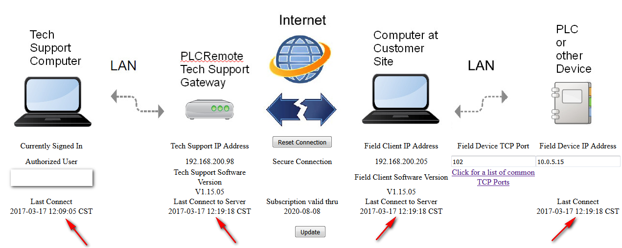
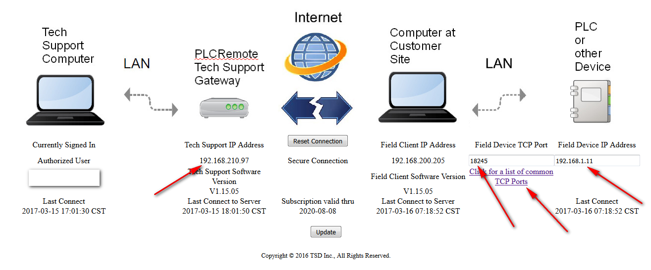
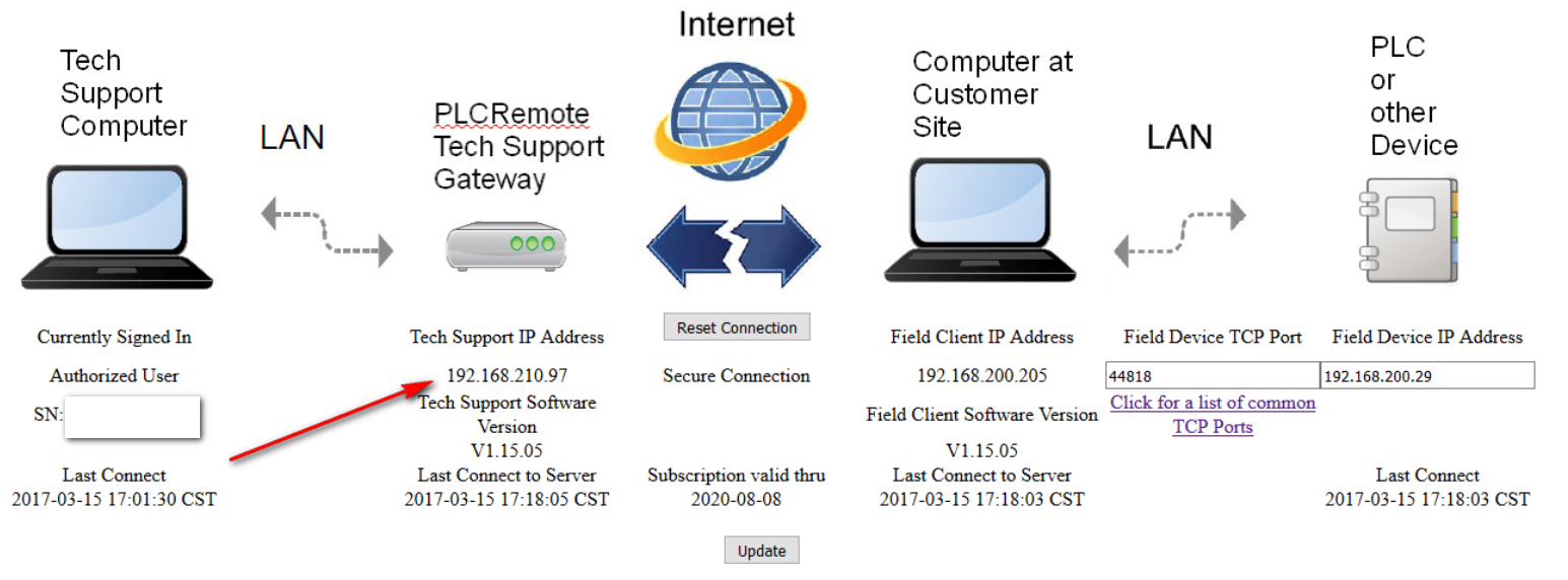
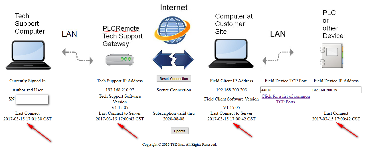
The PLC resided on a private 10.0.5.x subnet using a CP 343-1 ethernet module. First login to your web page “Manage My Remote” on the plcremote.net website. We saw the screen below:
(Click on images below to enlarge)
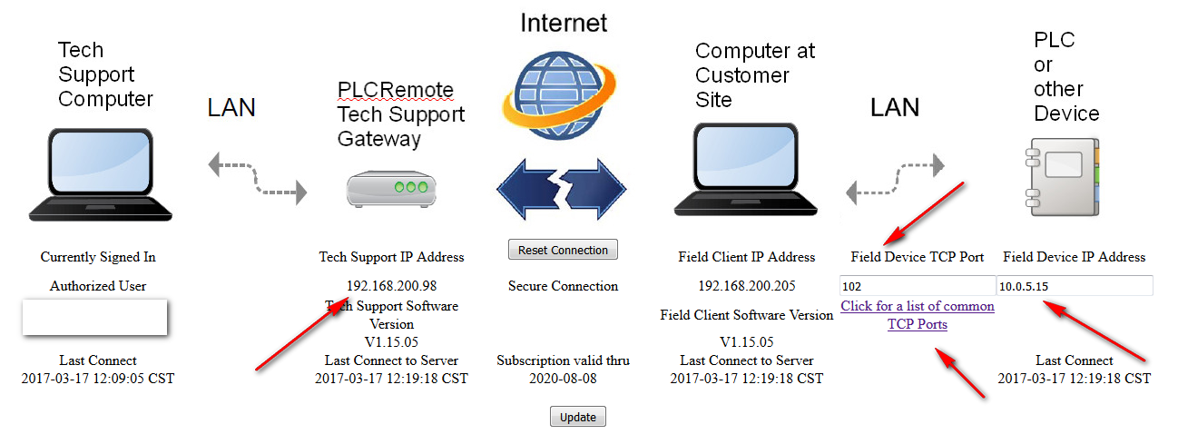
We entered the Field Device TCP Port number 102 which was found by clicking on, “Click for a list of common TCP Ports” shown on the “Manage My Remote” screen, and we entered the hardware configured IP address of the PLC as 10.0.5.15 in the Field Device IP Address box.
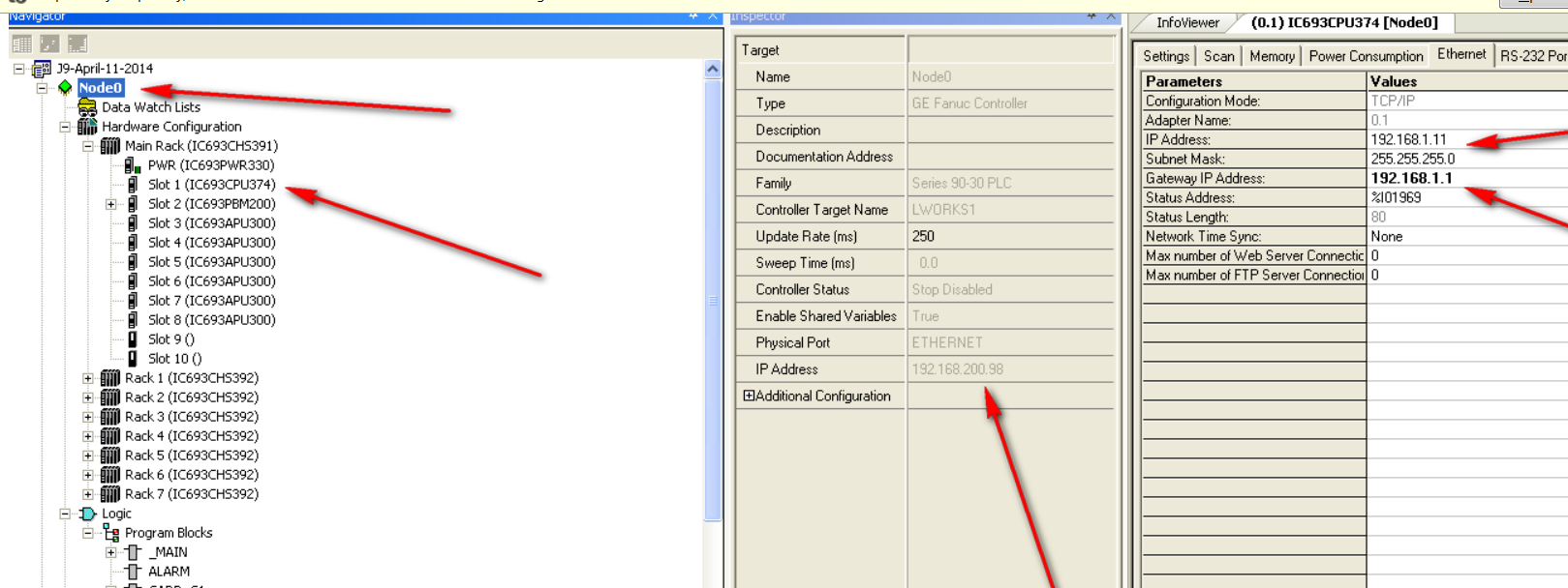
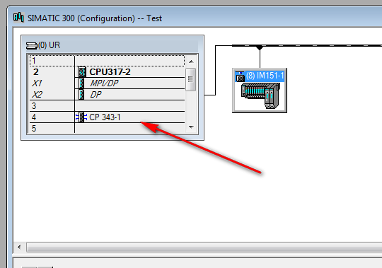
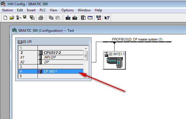
Next open the Siemens project and find the Hardware configuration line as shown and by double clicking open the Hardware configuration screen.
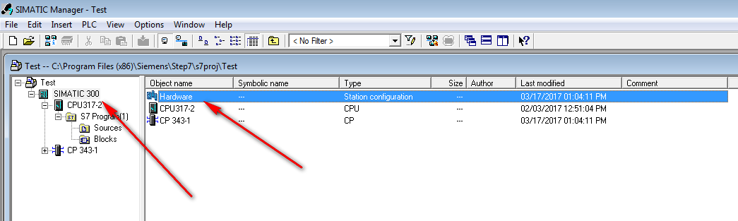
Then double click on the etherne module as shown below:
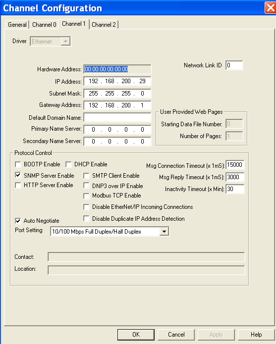
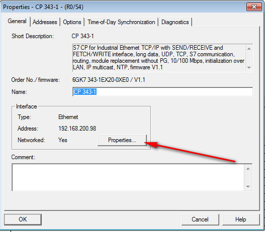
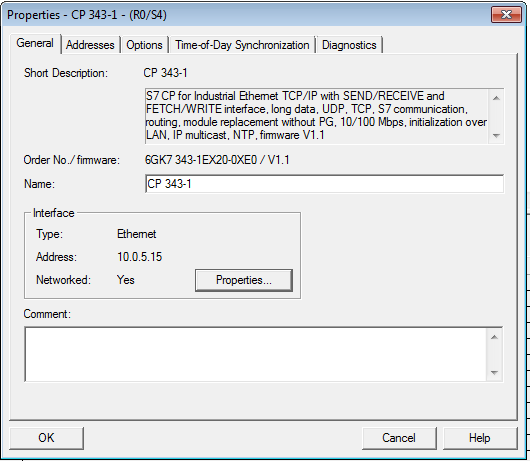
This opens the Properties box for this ethernet module. We are going to temporarily change the IP address in the project only, and then restore it later after we finish this session. Click on the properties box as shown below:
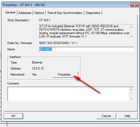
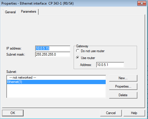
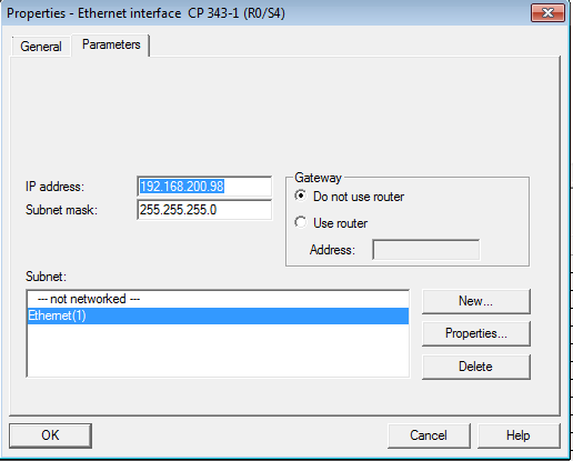
Record the IP address and Router address if it is used before making changes.
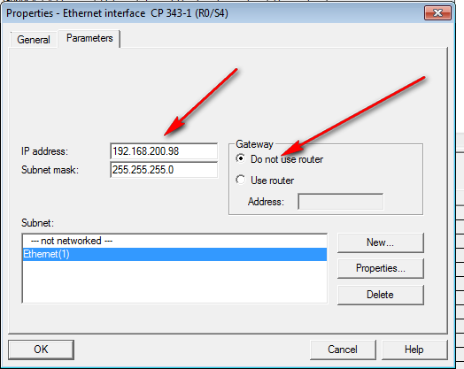
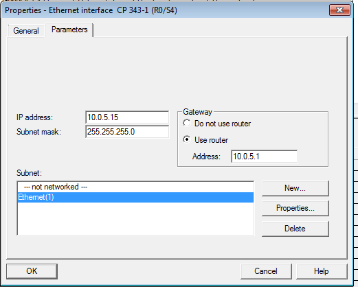
We changed the IP address to match that of our technical support gateway, and the subnet mask must be the same as the technical support gateway subnet. We also, checked do not use router as it is not required since our tech support gateway is on the same subnet as our development PC that is running the Step 7 development software. Then advance by clicking OK.
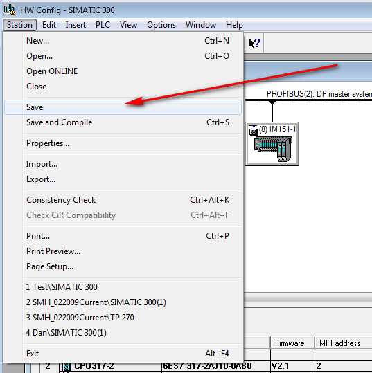
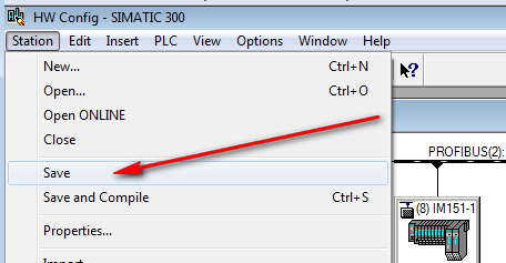
Then save the configuration (remember this just saves it in the windows PC project only, be careful not to do any hardware configuration updates on this PLC ethernet module. In our test we are just going online with the PLC to observe a VAT table.
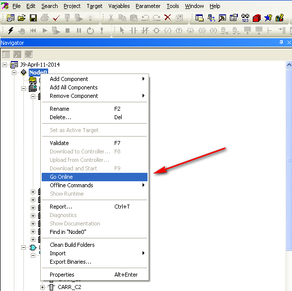
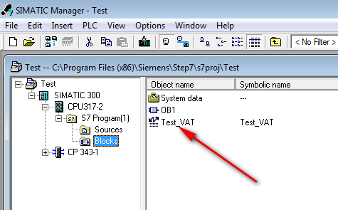
Next we go back to the main Simatic Manager and open Test VAT
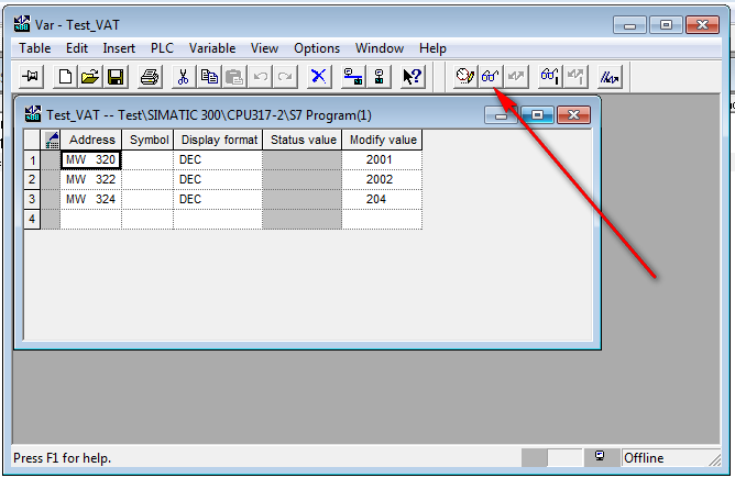
Then we click on the eye glasses which puts this VAT online with the PLC and also puts the VAT table into live monitoring mode.
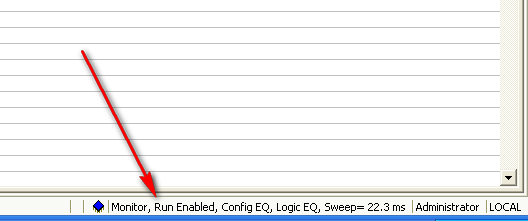
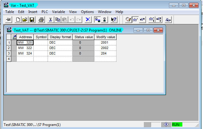
The status below shows connected to the PLC.
Now we are done with our monitoring, so we go back to the Hardware configuration screen and open the Ethernet module to reset its properties back to their original state.
Open properties.
Change these IP addresses back to the original settings.
Original settings are shown restored below.
Press OK.
Save the hardware configuration which only saves into the local windows PC project files.
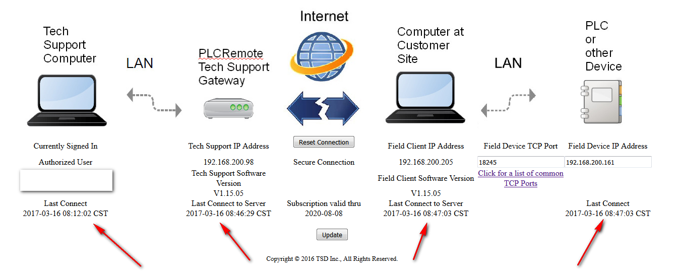
As a diagnostic check, a successful connection will show a current time stamp status on all devices as shown below on the web page “Manage My Remote” on the plcremote.net website. If one of the time stamps is not current, then this could indicate an issue with that device or the connection of that device.